


Aircraft Antenna installation
_____________________________________________________
_____________________________________________________
AIRCRAFT ANTENNA INSTALLATIONS
36. PERFORMANCE.
For proper performance, it is important that the radio equipment manufacturer's instructions be carefully followed in matching and coupling the antenna to the radio equipment.
a. The location of the antenna is of primary importance. When selecting a mounting position, consideration should be given but not limited to the following:
(1) Obstruction to signal reception by aircraft or aircraft components.
(2) Ignition noise (RF radiation pickup).
(3) Vibration.
(4) Flutter.
(5) Instrument static source interference.
|
|
|
b. Attach antenna mounting (masts, base receptacles, and/or supporting brackets) so that the loads imposed (for example, air, ice, etc.) are transmitted to the aircraft structure.
37. VHF ANTENNA - WHIP.
a. Locate this type antenna so that there is a minimum of structure between it and the ground radio stations. The antenna may be mounted on the top or bottom of the fuselage. It is not advisable to mount the antenna on the cowl forward of the windshield because a lightning strike might possibly blind the pilot.
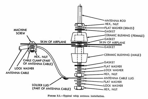
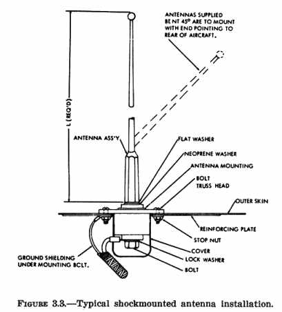
b. Methods of securing whip antennas to the structure are shown in figures 3.1 and 3.3.
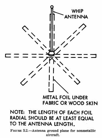
c. On fabric covered aircraft or aircraft with other types of nonmetallic skin, the manufacturer's recommendations should be followed in order to provide the necessary ground plane. An acceptable method of accomplishing this is by providing a number of metal foil strips in a radial position from the antenna base and secured under the fabric or wood skin of the aircraft. (See figure 3.2)
_____________________________________________________
38. VHF ANTENNA - RIGID.
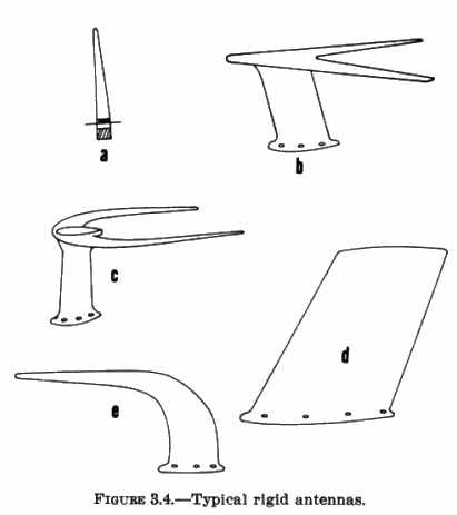
a. When it is necessary to cover a broader frequency range than can be covered by a whip antenna, a blade type should be used because it is resonant over a much broader frequency range. However, a broadband antenna is not as efficient as a small diameter whip antenna and, accordingly, should not be used with relatively low output transmitters (under 5 watts).
(1) The antennas shown in figure 3.4 are normally installed at a point on the fuselage directly above the cabin or baggage compartment.
When a rigid antenna is installed on the vertical stabilizer, evaluate the flutter and vibration characteristics of the installation.
(2) The approximate drag load an antenna is required to withstand can be determined by the following formula:
D = 0.000327 x A x V^2
(The formula includes a 90 percent reduction factor for streamline shape of antenna.)
Where D is the drag load on the antenna in
pounds,
A is the frontal area of the antenna in square feet, and
V is the Vne of the aircraft in mph.
The frontal area of typical antennas are
approximately as follows:
b. Installation of Rigid Antennas.
(1) Place a template similar to figure 3.5 on the fore-and-aft centerline at the desired location. Drill the mounting holes and the correct diameter hole for the transmission line cable in the fuselage skin.
(2) Install a reinforcing doubler of sufficient thickness to reinforce the aircraft skin. The length and width of the plate should approximate that illustrated in figures 3.6 or 3.8.
(3) Install antenna on fuselage, making sure that the mounting bolts are tightened firmly against the reinforcing doubler, and that the mast is drawn tight against the gasket.
When a gasket is not used, seal the crack between the mast and fuselage with a sealer, such as zinc chromate paste or equivalent.
(4) Route transmission line cable to the receiver, secure the cable firmly along its entire length at intervals of approximately 2 feet, and take care to prevent fouling of control cables.
39. VHF NAVIGATION RECEIVING ANTENNAS.
Locate antennas for omnirange (VOR), and instrument landing system (ILS) localizer receivers at a position on the aircraft where they will have the greatest sensitivity for the desired signals and minimum response to undesired signals such as electrical energy radiated by the engine ignition system. A good location for the VOR localizer receiving antenna on many small
airplanes is over the forward part of the cabin. Mount the rigid V-type antenna so that the apex of the "V" points forward and the plane of the "V" is level in normal flight. {See Figure 3.7.}
a. VOR Antenna Balun and Transmission Lines.
A dual element or balanced antenna system requires a balun or an impedance matching device for maximum signal transfer into an unbalanced coaxial cable. Rigid antennas, as displayed in figure 3.4, incorporate a balun as an integral component of the antenna assembly. Follow the manufacturer's installation procedures and assure that the balun is properly grounded to the airframe. Refer to AC 43.13-1A "Acceptable Methods, Techniques, and Practices - Aircraft Inspection and Repair" chapter 11, for acceptable bonding practices. {See Figure 3.9.}
(1) {(2) in original - Ed.} Figure 3.10 is an illustration of a typical VOR antenna balun. A balun made from a section of the transmission line functions as a tuned circuit or transformer which produces a standing wave ratio to provide the desired matching impedance. When the antenna is matched to the line, the line measurement in multiples of wave lengths is not critical.
(2) Radio wave velocity is less in a cable than in air; therefore, the wave length in cable will be shorter than in air. Appropriate test equipment must be used for transmission line measurements because the physical and electrical lengths of lines are not always equal.
(3) The transmission line should be kept as short as possible. Any bends in the cable should have at least a 3 inch radius. Follow the equipment manufacturer's recommendations regarding transmission lines and lengths.
b. Assembly of Coaxial Cable Connectors.
Optimum performance of a radio system is dependent upon the coaxial cable connector assembly. Follow the manufacturer's assembly instructions. Assure that the cable is not distorted or flattened when cutting. The electrical characteristics of the cable change when flattened or bent sharply.
(1) To remove the outer jacket, cut with a sharp knife around the circumference, then make a lengthwise slit and peel off the outer jacket. Do not nick, cut or damage the shield.
(2) Comb out the braid and bend back to expose the dielectric. Use a sharp knife to cut the dielectric around the circumference, not quite through to the center conductor. Do not nick or cut the conductor. Remove the dielectric by twisting and pulling. {See Figure 3.11.}
(3) Solder the contact to the center conductor. Use a clean, well-tinned soldering iron. {See Figure 3.12.}
(4) Do not apply
heat too long as this will swell the dielectric and make it difficult to insert into the body of the connector.
{See Figure 3.13.}
(5) Install connector body and tighten until secure. Do not over tighten as this will distort the cable. {See Figure 3.14.}
(6) Use only the crimping tool recommended by the manufacturer, or an equivalent tool when installing connectors which utilize a crimp-type contact.
c. Dual VOR/NAV Receiver Installations.
Two VOR
navigation receivers can be connected to a common VOR antenna. This is accomplished by utilizing a coaxial tee connecter (UG-274 A/U) and matched 0.5 wavelength coaxial cable lengths connected
from the tee connector to the respective VOR receivers. Typical cable lengths are from 22 to 35 inches and multiples of these lengths. Another method of coupling two VOR navigation receivers to a
common antenna is by utilizing a device called a coupler or diplexer. This device,
in addition to impedance matching, also provides isolation between VOR navigation receivers while keeping line insertion losses at a minimum.
...... segue al link
_____________________________________________________
http://avstop.com/maint/alterations/ch3.html
__________________________________________________________________________________________________________